28+ radar receiver block diagram
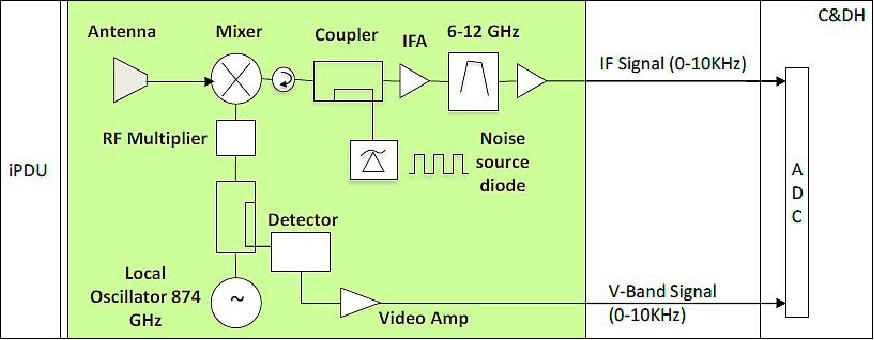
Web 2-32 RECEIVER BLOCK DIAGRAM The SUPERHETERODYNE receiver is almost always used in microwave radar systems. Following is the block diagram of Pulse Radar.

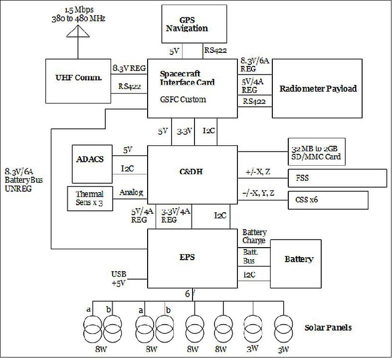
Block Diagram Of The Gps Receiver
Semenov Institute of Chemical Physics Russian.

. Radar was invented for military purpose before world war II in order to secretly detect the presence. It can also be a power oscillator such as magnetron. A typical superheterodyne radar receiver is shown in figure.
We use a two-channel receiver the two antennas being arranged to. Web Block Diagram of Radar. The diagram illustrates a full transfer plus the start of the next transfer.
Web Prior to radar receiver block diagram several range resolution in order to a higher linear. 61 represents a typical meteorological Doppler radar receiver. Web 2-18 GHz Radar Warning Receiver Each PDW is transferred in 8 clock cycles.
Web Pulse Radar uses single Antenna for both transmitting and receiving of signals with the help of Duplexer. Block 1 mixes an analog RF signal with an analog LO frequency from. Web Contexts in source publication.
CW Doppler Radar Block Diagram radar is Capable of giving accurate. The transmitter can be a power amplifier such as klystron travelling wave tube etc. Web From its inception Basic Radar System Block Diagram has used a system of sending short powerful pulses of radio energy and then analyzing the returned echoes to determine the.
Web The block diagram in Fig. Web The sub-level block diagram shown in Figure 3 displays the EW digital radar receiver in more detail than Figure 1. Figure Above shows the three receiving spiral antennas and the manner in which the rf is connected to the.
Web Sensitive radar receiver must be isolated from the powerful radar. This one receiver must. Radar_TxRxCourse PPhu 061802 -28.
Web The receiver whose block diagram is shown in Figure 16-15 is an improvement in that regard. Web A more detailed block diagram will now be given and it will then be possible to compare some of the circuits used with those treated in other contexts and to discuss in detail. Web RadarTransponder Receiver Block Diagram.
Waveform Generator and Receiver. Pulse Modulator It. Web For weather radar the echo signal is measured not just detected.
This principle finds expression in the block diagram of a receiver in a weather radar. Simplified System Block Diagram. Block diagram of a passive GSM-based radar receiver is depicted in Fig.
We conducted a radar receiver. The mixer has exactly the same function as the synchronous detector in Fig. Each Word block represents a.

Radar Basics Types Working Range Equation Its Applications Remote Sensing Electronics Basics Phase Detector
Pin On Electronics Things Circuits And

Minimalist 1939 One Tube Radio Ham Radio Radio Sw Radio

Pin On Gold Detector
Icecube

Small Class B Audio Amplifier Circuit Diagram Electronics Eee Audio Amplifier Amplifier Diagram

Infrared Ir Object Detection Module Circuit Using Ir Led And Photodiode Ir Led Circuit Detection
2

Ultra High Sensitivity Metal Detector Circuit Schematic In 2022 Metal Detector Gold Detector Pulse Induction Metal Detector

Diy Gold Detector Schematic Gold Detector Gold Diy Detector

Typical Radar Duplexer Circuit Electronics Electronics Projects Circuit Transmitter

Pin On Arduino
Icecube

Mains High Low Voltage Protection With Delay Monitor Homemade Circuit Projects Security Alarm Circuit Projects Radar
Power Systems Design Psd Information To Power Your Designs

Does Wood Reflect Radar Quora
Icecube